

PATHS-UP1-R-Glucose_BarcodeFigure_V3 w caption (1)
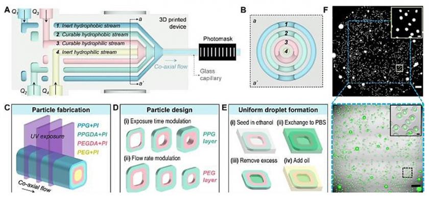
The figure depicts amphiphilic particle design, fabrication, and dropicle formation. (A) Schematic of the 3D-printed coaxial flow device with a glass capillary connected to the outlet. Inert and UV-curable hydrophobic and hydrophilic polymer precursors, pumped from separate inlets, flow through coaxially stacked channels separated by thin walls. A photomask atop the outlet capillary is used to shine UV light through rectangular slits. (B) A cross-section (aa’) of the device (A) shows four concentric channels. (C) Rectangular beams of UV light intercept co-axial flows of precursor streams, where two of the curable streams (PPGDA+PI and PEGDA+PI) are polymerized upon UV exposure in the form of concentric particles. The inert streams (PPG+PI and PEG+PI) act as sheath flows defining the inner and outer boundaries of the particles. (D) Amphiphilic particles with hydrophilic cores (PEGDA) and hydrophobic exteriors (PPGDA) of different designs are cured by tuning the UV exposure time or the flow rate ratios. (E) Workflow dropicle formation is shown: (i) particles are seeded in ethanol; (ii) the media is exchanged for PBS; (iii) excess fluid is removed as a tiny droplet is trapped within the hydrophilic core of the particle; (iv) oil is added to encapsulate the aqueous droplet. (F) A whole well (24-wellplate) fluorescence image at the top shows >1000 dropicles. An overlay image below it shows green color droplets within the particle cavities. The scale bars are 1mm and 100µm for the field of view and the inset, respectively.